Introduction
For most community wireless networks, installing a few rooftop and window nodes will fit the needs of the neighborhood or town. For others, more complex installations and configurations will be required. This guide follows and is an advanced companion to Common Hardware Setups, which covers the most common and basic Commotion configurations.
Sometimes you will need to connect multiple nodes together at a single site, and this guide will help you do that. Some of the instructions below require some familiarity with networking concepts, so we recommend reading through Learn Networking Basics first.
Jump to the solution you need
- Mesh with Ethernet with DHCP
- Mesh with Ethernet with Static IPs
- Mesh with Ethernet with a Static Gateway
Mesh with Ethernet with DHCP
Using a gateway to the Internet with DHCP for automatic assignment of IP addresses
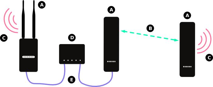
If you want to provide a gateway connection to the Internet on your mesh network, it helps to use several nodes at the location hosting that connection. This should reduce bottlenecks that would occur if there were only one node connected to that gateway.
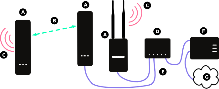
In the diagram above:
- (A) Represents a node running the Commotion software.
- (B) Represents the wireless mesh links between the nodes.
- (C) Represents the Access Point generated by the Commotion node for users to connect to.
- (D) Represents an Ethernet switch, which transfers data between all connected devices.
- (E) Represents Ethernet cabling connecting the modem and nodes to the Ethernet switch.
- (F) Represents the modem or router from the Internet Service Provider (ISP), connected to the Internet. It provides IP addresses on the local port with DHCP.
- (G) Represents the Internet.
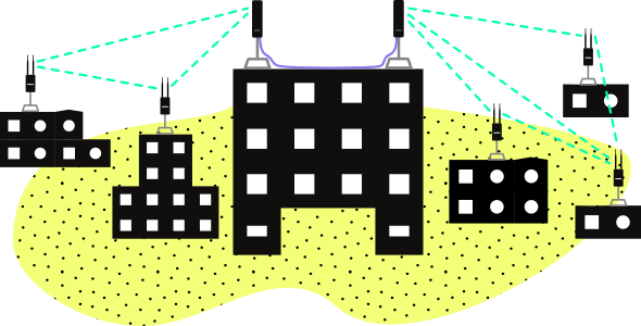
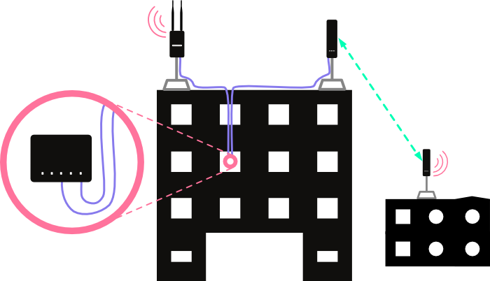
The diagram below demonstrates what this would look like with equipment installed on a building:
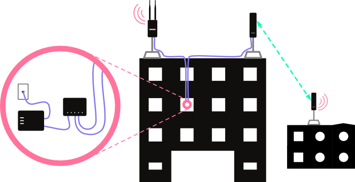
Steps to Configure: First, ensure the Commotion nodes mesh with wireless neighbors. Run the Setup Wizard on the first boot, with the same Mesh network name, Wireless channel, and Mesh encryption password.
You should also configure the node to allow connections on the Ethernet port to the Administration interface. Follow the instructions for “Opening the firewall for remote Administration” in Advanced Commotion mesh settings.
Set to Receive DHCP only
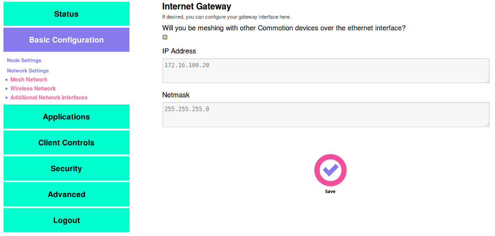
Now, set the nodes to “gateway only” to prevent issues with the nodes booting before the modem. Browse to the Administration panel on the node. Navigate to the Basic Configuration -> Network Settings -> Additional Network Interfaces menu.
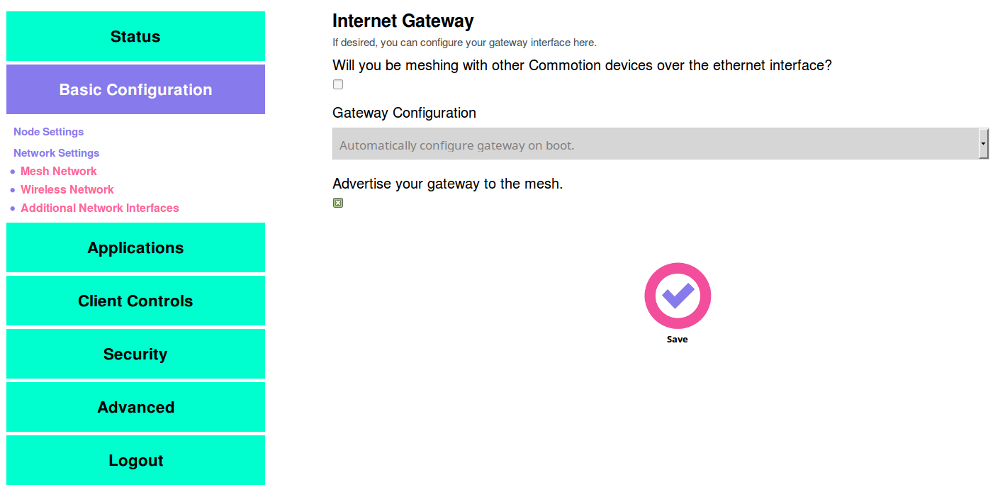
- In the “Gateway Configuration” pull-down menu, select “This device should ALWAYS try to acquire a DHCP lease”, and make sure “Advertise your gateway to the mesh” is checked.
- Save, then Save and apply these settings.
Enable meshing over the Ethernet port
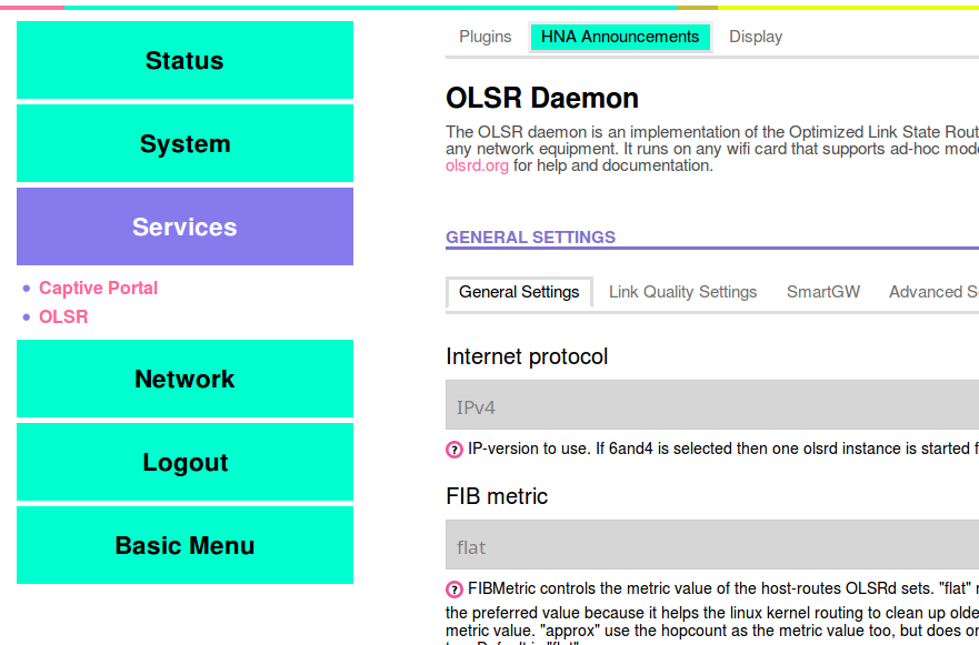
Next, enable meshing over Ethernet for the nodes connected to the switch. Navigate to to the Advanced -> Services -> OLSR menu.
At the bottom of the page, under the interfaces section, click on the “Add” button.
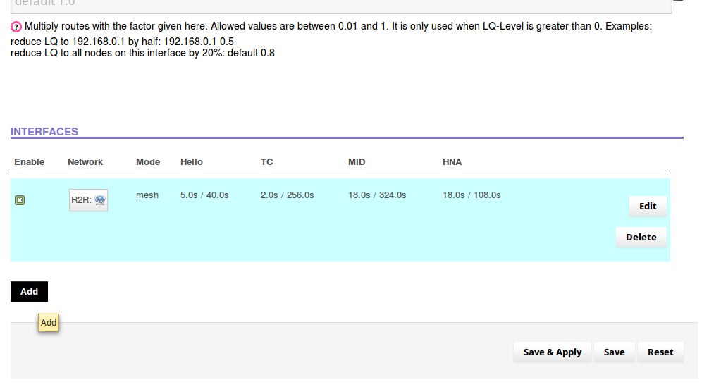
- On the next page, click radio button for the “WAN” interface under “Network”.
- In the “Mode” pull down menu, select “Ether”.
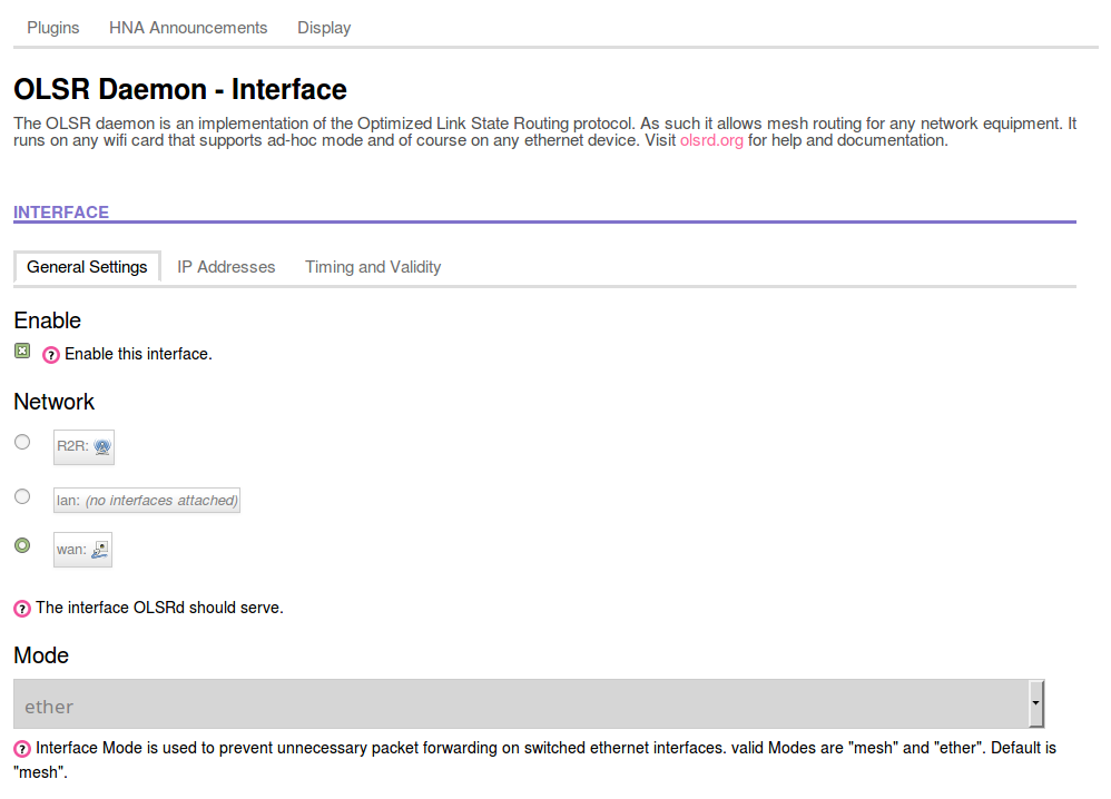
Scroll to the bottom of the page and “Save and Apply” these changes.
Change Firewall Settings
Finally, adjust the Firewall so mesh traffic can pass through in both directions. Navigate to the Advanced -> Network -> Firewall menu. Scroll down to the bottom of the page, to the section that is titled “Zones”. It should look like this:
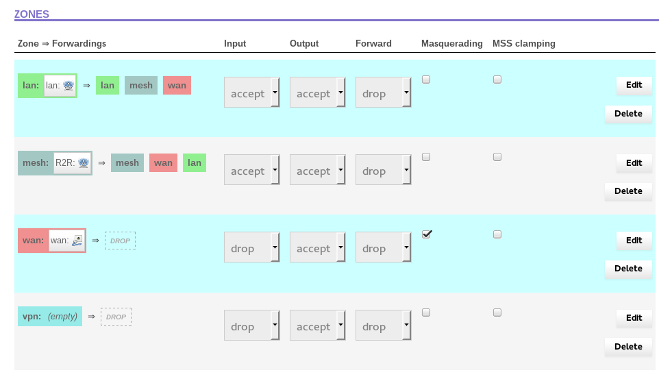
Click the “Edit” button in the WAN row – it should open up the Firewall – Zone Settings – Zone
“wan” page. Scroll down until you see the section that says “Inter-zone forwarding”. It should look
like this:
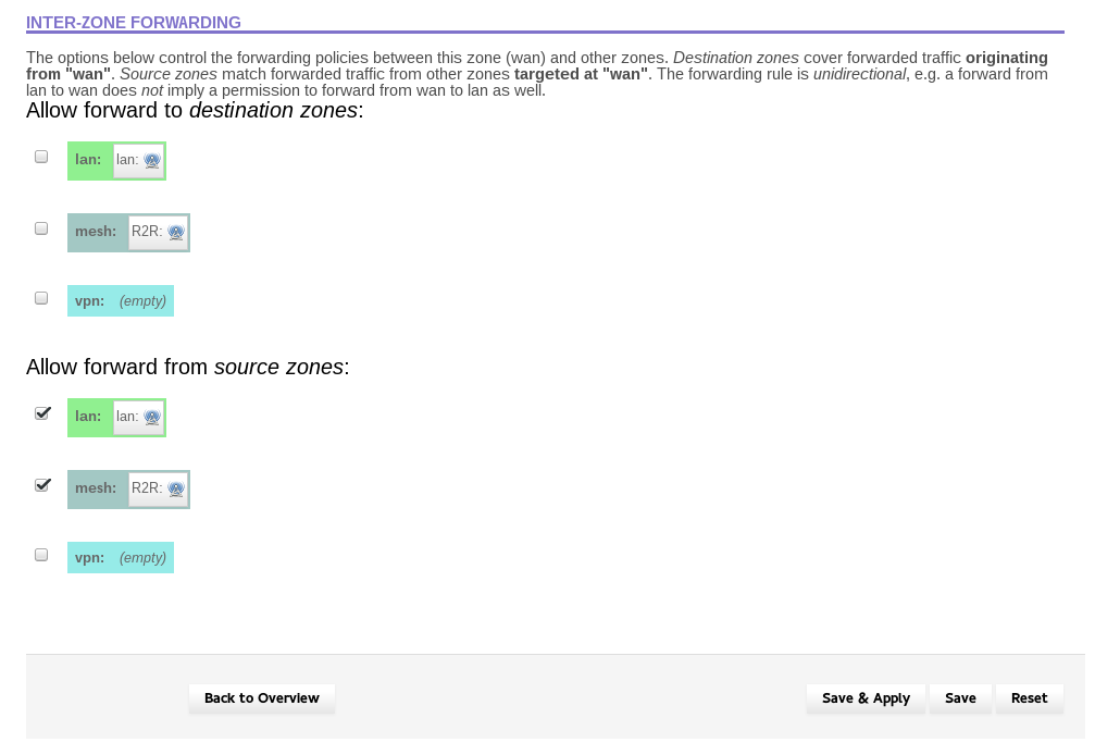
Under “Allow forward to destination zones”, click the boxes next to “lan” and “mesh”. This will enable
traffic to pass from WAN to LAN and MESH. The screen should now look like:
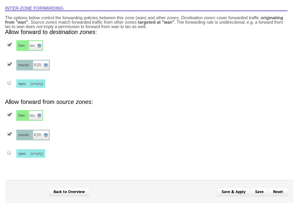
Hit “Save & Apply”. Click on “General Settings” at the top of the page. You should be returned to the
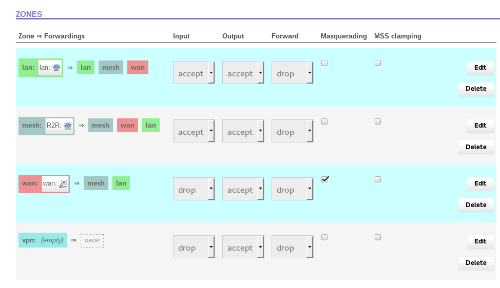
“Firewall – Zone Settings” page. Scroll down and look at the table of zones. It should look like this:
Reboot and Verify
Reboot the router to verify the settings.
- Browse to Advanced -> System -> Reboot.
- Click “Perform reboot” and wait for the device to restart.
Do these steps for each Commotion node connected to the switch. When all the nodes have been configured, you can confirm that they are meshing over the wired Ethernet connections by connecting to one of the nodes and browsing to the Basic Menu -> Status. Then click on “Nearby Mesh Devices” and look under the “OLSR Links” section. You should see entries for all of the nodes connected to the switch, and they should have IP addresses on the same subnet, as given out by the modem or router. These will look like 192.168.x.y, or 10.0.x.y, or something similar. That entry will have an ETX value of 0.100. If this is the case, the nodes are successfully meshing with Ethernet.
Tip: Mounting wireless routers very close to each other can cause interference. For best performance, we recommend mounting equipment on separate poles, with two or three meters (6 to 10 feet) between them and using metal shields on the back of directional nodes. These reduce the wireless signal radiated from the back of the equipment, reducing the interference. You can buy these commercially, or make your own from metal building studs.
Mesh with Ethernet with Static addressing
Static IP addresses, without a Gateway to the Internet
Even if a tall or centrally located site doesn’t have a gateway to the Internet, it may help to mount several wireless nodes there to act as a “supernode” on the network. This can increase throughput on the network and reduce bottlenecks for very busy nodes or nodes with many, many connections on the mesh.
In the diagram above:
- (A) Represents a node running the Commotion software.
- (B) Represents the wireless mesh links between the nodes.
- (C) Represents the Access Point generated by the Commotion node for users to connect to.
- (D) Represents an Ethernet switch, which transfers data between all connected devices.
- (E) Represents Ethernet cabling connecting the modem and nodes to the Ethernet switch.
The diagram below demonstrates what this would look like with equipment installed on a building:
Steps to Configure: First, ensure the Commotion nodes mesh with wireless neighbors. Run the Setup Wizard on the first boot, with the same Mesh network name, Wireless channel, and Mesh encryption password.
You should also configure the node to allow connections on the Ethernet port to the Administration interface. Follow the instructions for “Opening the firewall for remote Administration” in Advanced Commotion mesh settings.
The nodes connected to the switch will not receive IP addresses, since there is no modem or router. If the node was previously connected to a router with a DHCP server, disconnect each node and reboot them after running Setup Wizard. This will ensure the nodes do not have incorrect IP address information.
Change the WAN port to use Static Addressing
Browse to the Administration panel on the node.
- In the Basic Configuration menus, go to the Network Settings -> Additional Network Interfaces menu
- Select the box under “Will you be meshing with other Commotion devices over the Ethernet interface?”. The page will change and two fields will appear.
- Put in a static IP address and Netmask for this router.
If you are adding the router to the same switch with others that are meshing over Ethernet, use an IP address in the same range. For example, if a node had the address 172.16.10.5, you could use 172.16.10.6.
If you are setting up mesh over Ethernet at a new site, use an IP address range that isn’t in use somewhere else. For example, if the 172.16.10.x range is in use somewhere, don’t use it again – this will cause problems on the network. You could use 172.16.11.x, 10.50.0.x, or something else. It is recommended not to use 192.168.x.x since many home and office routers use these ranges.
The Netmask will almost always be 255.255.255.0.
Enable meshing over the Ethernet port
Next, enable meshing over Ethernet for the nodes connected to the switch. Navigate to to the Advanced -> Services -> OLSR menu.
At the bottom of the page, under the interfaces section, click on the “Add” button.
- On the next page, click radio button for the “WAN” interface under “Network”.
- In the “Mode” pull down menu, select “Ether”.
Scroll to the bottom of the page and “Save and Apply” these changes.
Change Firewall Settings
Finally, adjust the Firewall so mesh traffic can pass through in both directions. Navigate to the Advanced -> Network -> Firewall menu. Scroll down to the bottom of the page, to the section that is titled “Zones”. It should look like this:
Click the “Edit” button in the WAN row – it should open up the Firewall – Zone Settings – Zone
“wan” page. Scroll down until you see the section that says “Inter-zone forwarding”. It should look
like this:
Under “Allow forward to destination zones”, click the boxes next to “lan” and “mesh”. This will enable
traffic to pass from WAN to LAN and MESH. The screen should now look like:
Hit “Save & Apply”. Click on “General Settings” at the top of the page. You should be returned to the
“Firewall – Zone Settings” page. Scroll down and look at the table of zones. It should look like this:
Add a HNA to the Static IP range
Add a Host Network Announcement (HNA) for the Static IP address range for the nodes. This setting lets the rest of the mesh network know where to find anything attached to the switch that might have those Static IPs.
Go to Advanced → Services → OLSR, and click on “HNA Announcements” at the top of the page.
Click the “Add” button to create a new line, and put the following settings into the boxes:
- Network address: your static IP range, ending with a zero
- Netmask: 255.255.255.0
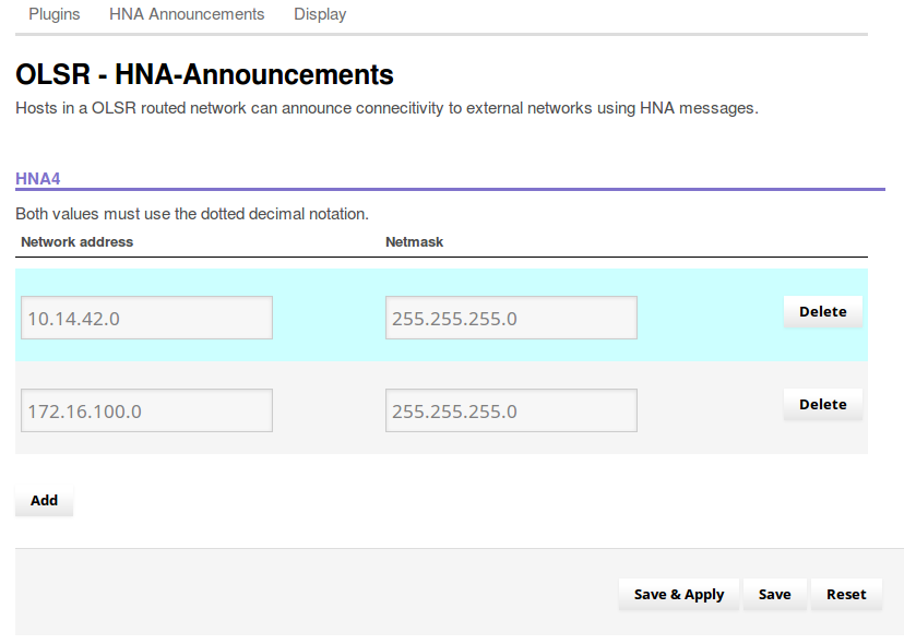
At the bottom of the page, hit “Save & Apply”.
Reboot and Verify
Finally, plug each node into the switch and reboot the node one more time. This will ensure the IP address configurations are in the correct state.
- Browse to Advanced -> System -> Reboot.
- Click “Perform reboot” and wait for the device to restart.
Do these steps for each Commotion node connected to the switch. When all the nodes have been configured, you can confirm that they are meshing over the wired Ethernet connections by connecting to one of the nodes and browsing to the Basic Menu -> Status. Then click on “Nearby Mesh Devices” and look under the “OLSR Links” section. You should see entries for all of the nodes connected to the switch, and they should have IP addresses on the same subnet, as given out by the modem or router. These will look like 192.168.x.y, or 10.0.x.y, or something similar. That entry will have an ETX value of 0.100. If this is the case, the nodes are successfully meshing with Ethernet.
Tip: Mounting wireless routers very close to each other can cause interference. For best performance, we recommend mounting equipment on separate poles, with two or three meters (6 to 10 feet) between them and using metal shields on the back of directional nodes. These reduce the wireless signal radiated from the back of the equipment, reducing the interference. You can buy these commercially, or make your own from metal building studs.
Mesh with Ethernet with a Static Gateway
Using Static IP addressing, with a Gateway to the Internet
This example is similar to the other example with a gateway above, but the gateway to the Internet does not provide IP addresses automatically using DHCP. You must configure the addresses for the Commotion nodes manually. In this example the gateway IP address is 192.168.50.1, but you will need to obtain the proper IP address information from your Internet service provider.
In the diagram above:
- (A) Represents a node running the Commotion software.
- (B) Represents the wireless mesh links between the nodes.
- (C) Represents the Access Point generated by the Commotion node for users to connect to.
- (D) Represents an Ethernet switch, which transfers data between all connected devices.
- (E) Represents Ethernet cabling connecting the modem and nodes to the Ethernet switch.
- (F) Represents the modem or router from the Internet Service Provider (ISP), connected to the Internet. It is configured with a Static IP address, and does not provide IP addresses to clients automatically via DHCP.
- (G) Represents the Internet.
The diagram below demonstrates what this would look like with equipment installed on a building:
Steps to Configure: First, ensure the Commotion nodes mesh with wireless neighbors. Run the Setup Wizard on the first boot, with the same Mesh network name, Wireless channel, and Mesh encryption password.
You should also configure the node to allow connections on the Ethernet port to the Administration interface. Follow the instructions for “Opening the firewall for remote Administration” in Advanced Commotion mesh settings.
The nodes connected to the switch will not receive IP addresses, since there is no DHCP server. If the node was previously connected to a router with a DHCP server, disconnect each node and reboot them after running Setup Wizard. This will ensure the nodes do not have incorrect IP address information.
- Browse to Advanced -> System -> Reboot.
- Click “Perform reboot” and wait for the device to restart.
Change the WAN port to use Static Addressing
Browse to the Administration panel on the node.
- In the Basic Configuration menus, go to the Network Settings -> Additional Network Interfaces menu
- Select the box under “Will you be meshing with other Commotion devices over the Ethernet interface?”. The page will change and two fields will appear.
- Put in a static IP address and Netmask for this router.
The static IP that you choose should be in the same range as the IP address of the router that has the connection to the Internet. For example, if the gateway’s IP is 10.50.0.1, you would choose a static IP for the node in the 10.50.0.x range, where “x” is a number that isn’t in use by any other nodes, servers, or devices.
The Netmask will almost always be 255.255.255.0.
Set a Static Gateway
Configure the node with a static route to the Internet. Browse to the Administration panel on the first node. Go to the Advanced -> Network -> Static Routes menu.
- Click “Add” in the “Static IPv4 Routes” section.
- In the entry that comes up, select “WAN” in the first pull-down menu.
- In the “Target” field, enter 0.0.0.0
- In the “IPv4-Netmask” field, enter 0.0.0.0
- In the “IPv4-Gateway” field, enter the IP address for the gateway modem or router.
- Save and apply these settings.
Enable meshing over the Ethernet port
Next, enable meshing over Ethernet for the nodes connected to the switch. Navigate to to the Advanced -> Services -> OLSR menu.
At the bottom of the page, under the interfaces section, click on the “Add” button.
- On the next page, click radio button for the “WAN” interface under “Network”.
- In the “Mode” pull down menu, select “Ether”.
Scroll to the bottom of the page and “Save and Apply” these changes.
Change Firewall Settings
Finally, adjust the Firewall so mesh traffic can pass through in both directions. Navigate to the Advanced -> Network -> Firewall menu. Scroll down to the bottom of the page, to the section that is titled “Zones”. It should look like this:
Click the “Edit” button in the WAN row – it should open up the Firewall – Zone Settings – Zone
“wan” page. Scroll down until you see the section that says “Inter-zone forwarding”. It should look
like this:
Under “Allow forward to destination zones”, click the boxes next to “lan” and “mesh”. This will enable
traffic to pass from WAN to LAN and MESH. The screen should now look like:
Hit “Save & Apply”. Click on “General Settings” at the top of the page. You should be returned to the
“Firewall – Zone Settings” page. Scroll down and look at the table of zones. It should look like this:
Add a HNA to the Static IP range
Add a Host Network Announcement (HNA) for the Static IP address range for the nodes. This setting lets the rest of the mesh network know where to find anything attached to the switch that might have those Static IPs.
Go to Advanced → Services → OLSR, and click on “HNA Announcements” at the top of the page.
Click the “Add” button to create a new line, and put the following settings into the boxes:
- Network address: your static IP range, ending with a zero
- Netmask: 255.255.255.0
At the bottom of the page, hit “Save & Apply”.
Finally, plug each node into the switch and reboot the node one more time. This will ensure the IP address configurations are in the correct state.
- Browse to Advanced -> System -> Reboot.
- Click “Perform reboot” and wait for the device to restart.
Do these steps for each Commotion node connected to the switch. When all the nodes have been configured, you can confirm that they are meshing over the wired Ethernet connections by connecting to one of the nodes and browsing to the Basic Menu -> Status. Then click on “Nearby Mesh Devices” and look under the “OLSR Links” section. You should see entries for all of the nodes connected to the switch, and they should have IP addresses on the same subnet, as given out by the modem or router. These will look like 192.168.x.y, or 10.0.x.y, or something similar. That entry will have an ETX value of 0.100. If this is the case, the nodes are successfully meshing with Ethernet.
Tip: Mounting wireless routers very close to each other can cause interference. For best performance, we recommend mounting equipment on separate poles, with two or three meters (6 to 10 feet) between them and using metal shields on the back of directional nodes. These reduce the wireless signal radiated from the back of the equipment, reducing the interference. You can buy these commercially, or make your own from metal building studs.
Definitions
- AP (Access Point)
- A device that allows wireless devices to connect to a wired network using Wi-Fi or related standards
- DHCP
- Dynamic Host Configuration Protocol. This assigns IP addresses to client devices, such as desktop computers, laptops, and phones, when they are plugged into Ethernet or connect to Wireless networks.
- Ethernet
- A type of networking protocol - it defines the types of cables and connections that are used to wire computers, switches, and routers together. Most often Ethernet cabling is Category 5 or 6, made up of twisted pair wiring similar to phone cables.
- Router
- A device that determines how messages move through a computer network.
- Node
- An individual device in a mesh network.
- WAN
- Wide Area Network. This signifies the connection to the global Internet or a different, typically larger, network.